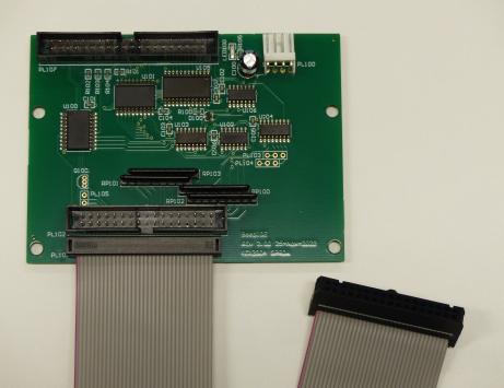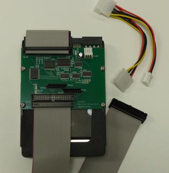

The original drives used the SASI interface (largely equivalent to a SCSI I interface) which made writing the hardware drivers relatively simple, using high level "sector" operations to talk to the logical layout of the drive. There were also Winchester drives using a proprietary interface between the micro and the drive itself.
However this approach has a number of drawbacks
There are four locating holes spaced to allow the entire interface board to be screwed onto the holes normally intended to hold the drive in the PC case, though that's not essential and the holes could just be used for alternative mounting in a box.

Jumper links on the PCB determine where in the memory map the drives appear to software, each interface taking 16 bytes in the range &FC40-FC4F or &FC50-FC5F as desired. As each interface can drive a master/slave combination this gives a potential for up to 4 IDE drives in total by using two interfaces with the address jumpers set in opposite senses.
Though filing system software would be required, there's no reason in principle why an ATAPI device could not appear amongst the 4 drives - opening up the possibility of support for CD-ROM as well as harddisc storage.
Jumpers define the region in the memory map which the interface appears, with &FC40 being the default. Within this the decoding selects:
| Offset | Description | Access |
| +00 | data (low byte) on CS0 | RW |
| +01 | error on CS0 | R |
| +02 | count on CS0 | RW |
| +03 | sector on CS0 | RW |
| +04 | cylinder (low) on CS0 | RW |
| +05 | cylinder (high) on CS0 | RW |
| +06 | head on CS0 | RW |
| +07 | status on CS0 | R |
| +08 | data (high byte) | RW |
| +09 | RW | |
| +0A | RW | |
| +0B | RW | |
| +0C | unused | |
| +0D | unused | |
| +0E | alternative status on CS1 | R |
| +0F | unused |
While the interface hardware supports 16 bit transfers to the drive, the 6502 is an 8 bit CPU, so the wider transfers must be completed in two stages:
Note that some registers have different meanings if the drive is programmed to run in logical block addressing mode. For a more complete description of what the registers mean consult the ATA command document.
The updated filing system ROM containing ADFS with support for IDE drives should be downloaded along with the formatting program, HDInit, written in BASIC.

| Option: | Price: | Comments: | ||||||
| PCB fully populated and tested |
| Fully populated PCB as shown above Includes approx 60cm of ribbon cable to the 1MHz bus port You will need a suitable 12V/5V power supply, drive, 40 way IDE cable, and ADFS ROM | ||||||
| PCB fully populated plus preformatted drive |
| Fully populated PCB as shown above Includes approx 60cm of ribbon cable to the 1MHz bus port Includes a molex 4 pin 'Y' adapter to power drive and interface board from a single inlet Includes a short interlinking data ribbon cable to the drive Supplied with preformatted drive with two maximum sized 512MB partitions (ie.a 1GB or larger drive) You will need a suitable 12V/5V power supply, and ADFS ROM |
